Saturday, 8 May 2010

Intrax suspension systems, camber and castor angles

When we wanted to use and sell the best suspension systems you can buy we went to Intrax, they didn't have a system so I offered to lend them the 16v to help them develope some.

I took the integrale with me, hopped on a North Sea ferry and met up with fellow Lancisti Michel Van Aggelen. Why? Because he's Dutch and I was in The Netherlands, he knows his country, integrales, suspension and is a friendly helpful kind of fella so was the best man for the job.

Photobucket

We made our way swiftly across the country, stopping briefly for a bite to eat and for Michel to take some pics of windmills.

We got to Intrax at about lunchtime, met up with 'Mr Intrax': Henk Thuis, discussed what we needed and what they could provide.

Photobucket

Henk has been racing some serious cars since 1993, Donkervoort, Alfa, BMW and currently a Porsche 996 which he won with in 2008, came runner up in 2009 and is currently doing well with in 2010.


After a quick tour of their premises which had some interesting Automotive machinery lurking in every corner (and large trophy cabinet)

Photobucket

I left the 'grale with them and it was back across the country in Michels 8v (well, you can't have everything) to a bar for a few beers before getting back onto the Ferry.

A few weeks later I was back to pick the car up, the guys there explained what they had done and Henk took me out for a drive, the car felt really tight and quick as he threw it around a local industrial estate.

The set up looks great, really well made and thought out:


We had some lunch and met up with another local Deltisti Bas Van Elten, I've been in contact with these guys for years via email so it was great to meet them in the flesh and have a good chat before heading off back to the ferry.

Back home and on track the grip is amazing, I met up with two customers, both 'grale drivers who could not get over how easy it was to corner at such high speeds, also with the addition of the thicker adjustable rear ARB set to 'dry' it changes direction through the tight left right flicks such as chicanes with superb composure.

A big thanks to Intrax and Michel, a big thumbs down to tightwads North Sea Ferries, Hull: If you want to go with a car and come back on foot they charge a very large premium, so I booked for a car both ways. On coming back with no car on the Dutch side it was no problem, I just showed my ticket, passport and walked on.
Trying to do the same on the UK side had me being pulled up at the check in desk and forced to pay a stupid amount of money to get on as a foot passenger.

Yes, you read that right, if you want to go on as a foot passenger and not take your car you are charged more!


Castor and camber


The Intrax strut top is available in different colours and is adjustable for camber and castor.

It's very difficult to find anything written about castor angles, I have several books on suspension and I think only one mentions why it can be important, advantageous and linked to camber.

Castor angle is the angle of the strut as viewed from the side:


Most people refer to it in connection with the directional stability of a car because this is its primary function, when you have more positive castor (viewed from the side, the top of the strut is further towards the back of the car) the steering self centres easier and the car is more stable in a straight line at high speed, the steering also becomes more heavy the more positive castor is applied.

This is Camber:


If the wheel leans in towards the car at the top then this is 'Negative camber'.

Basically, in order for the tyre to grip when cornering hard it needs to present itself flat to the tarmac so all of the surface of the tyre is working, camber gives us this. This is called 'Static camber' and whilst it comes into its own when cornering, it can be a compromise when braking or accelerating in a straight line when the tyre is at an angle to the road or track, both for traction and for tyre wear.

This is where positive castor angle (PCA) comes in and here is how it works:
The pencil is the strut with zero castor angle, the wheel (roll of tape) has zero camber angle, when we turn the 'wheel' it keeps the same angle, i.e, the tyre to road angle doesn't alter.


Now let's dial in some PCA:


The axis of the turned wheel has now altered and you see how it has affected the camber angle:


This is quite an exaggerated example, but it shows what is happening - the more you turn the wheel, the more camber is introduced.

Saturday, 10 April 2010

Flowbench testing

Just a bit of a write up this week on some parts brought in by Andrew Grogan for testing.
Andrew looked high and a low for a really good Evo 1 to do a restoration project on, but sadly settled for a Winner red.

He then proceeded to pull it to bits and is reconditioning everything which could be and replacing everything which couldn't, we are talking about a full-on nut and bolt restoration here, every step and every part has been methodically logged, pictured and written about and lot of people eagerly await the results of his years of hard work.

All results below were taken at 10" of depression.

First up on the flowbench was a mildly reprofiled throttle body, it looked really nice and I would have put money on it giving 2 or 3cfm extra, result? Zero improvement over standard.
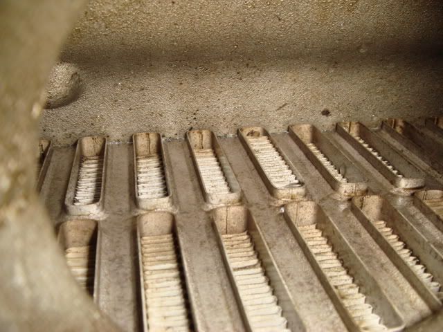
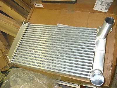
Well it could only get better and next up was a bit more interesting: An OE intercooler with the end tanks removed and a new more modern core welded inbetween them. The exit/entry pipes had been mildly re-profiled and polished, the quality of welding was superb and we counted less tubes than the OE 'cooler meaning it had larger section ones fitted. Looking into the core you could see it was a more aerodynamically friendly affair, but still tube and fin construction (see earlier intercooler article).


On the bench the OE intercooler flowed 153cfm.
The re-cored one flowed 165cfm.

So not a bad result for a simple core change and a bit of cleaning up, I think they could have got more by changing to a bar & plate type, or at least, it would have been interesting to test one anyhow. As outlined before if you want more power then get more airflow by trading up to larger section core, but if you want to keep your integrale looking standard whilst gaining a bit and lightly modernising it then it's not a bad mod.


Andrew then brought in a head he had done by someone without a flowbench so had no figures for it. It had been very tidily done, no major changes to the port geometry or valve and seat angles, just some rounding off of the short-side-radius and knife edging on the port splitter.


A stock head flows 137cfm
And his was up to 155cfm


So again a good modest improvement, high CFM figures aren't everything and I didn't have the time to do any valve-in tests.

We tested an OE cast iron log manifold on an umodified head V Andrews tubular item:


As you can see, nothing really unexpected, but interesting to see nonetheless. Looking closer at the figures, at least the tubulars best and worst flowing headers are within 10cfm of each other whilst the OE log has a much larger 18cfm difference.

This was supposed to be just a factual post on what we found out from the items tested, but lets wander off for a moment and look a bit closer at the usual manifold debate questions.

Are you going to see a non flow loss ex'manifold on an integrale which keeps the turbo in its original position? Well I think you're going to struggle! I'm saying this not only from what we have found here, but also because we have a life size model along with modelling kit in the workshop which we are making our own on so I know how difficult (impossible?) it is to create the perfect manifold.

Do you really need equal length tubes? Yes. Look at the tubular one on test, the shortest pipe has the worst CFM figure, it has this because of the number of bends and restrictions in it, so what if we build a manifold purely based on equal flow rates for all four pipes?
What is the point in an equal length manifold if the flow figures are all over the place?
Food for thought and open to discussion, but the answer for me would be equal length and equal flow.

Another widely debated topic is whether the integrale 16v inlet manifold is better than that of the Fiat Coupe, many people claim it is so we did a back to back test and found no difference between the two at all. Both showed a 36cfm loss when bolted to a head flowing 168cfm on cylinder No.1.

Sunday, 4 April 2010

Flowbench and cylinderheads

Some people don't realise we have a flowbench at Deltaparts.

Many people have no idea what one is so let me explain.


Ok, as previously discussed in an earlier post airflow is probably the most important thing to consider when trying to increase the power of your engine, if you can get more in and match it with more fuel you are going to get more power, simple.

How do you know if your modifications to the airways have done any good without checking the output of the engine? You don't unless you have a flowbench to give you a good idea of what is going on. You see, sometimes you can make things worse or spend a lot of time on something which gives little or no improvement.

Don't buy a reworked head from someone who cannot prove what they have done.

(Very!) basically a flowbench has a few electric fans inside it which draw a vacuum through the test hole, they can be reversed to blow and can also be controlled to give a certain airflow at which you take your readings at, the basic Superflow 110/120 is what many people have, it is rated at testing up to 100bhp per cylinder and maxes out at 185cfm (cubic feet per minute)

Ours is a bit bigger, it runs 6 motors and will pull your arm in if you get too close! It pulls over 28" and 250cfm quite easily. 28" is called test depression, it is read from a manometer which is T'd off from one of the chambers within the bench. The more vac and CFM you can pull the closer and more accurate to a real life situation you will get. Air is much heavier than you would think and (just like a car going round a bend) the faster it goes, the less chance it has of actually getting round smoothly so the more air your bench flows, the more accurate and closer to real life your results will be.

Whilst it has to be said that your own flowbench is better used with your own before & after figures it's sometimes good to compare with others, so the ability to be able to check at 10 or 28" is useful as not everyone uses the same test depression.

The Superflow has liquid filled manometers to take the readings which you manually log, we have digital ones on ours which are displayed on the laptop screen and can be logged into the laptop if needed. This makes the job much easier and quicker and photographing your good work a bit easier too as you will see.

With a fair bit of work we can get an integrale 16v bare inlet port up to 170cfm, it isn't just the high cfm numbers which you are chasing, you need good air speed throughout the port, no good if the air speed is too slow or too high even. We read airspeed in FPS (feet per second) with a probe which we can push into any part of the port to check for high, low or dead areas where nothing much is happening and shape the port to suit.
There isn't much point in beyond 170cfm BPF either if you are still using the OE sized valve or untouched inlet manifold as it will pull those figures back down once it is fitted.


Below is a graph of results from a head I did last week compared to standard. It shows the flow of the port with the valves fitted and at different lifts in increments of 1mm. Stock head versus modified which has a 3 angle valve seat too. It also shows a comparison at BPF (bare port flow) no valves fitted.


As you can see, it flows more air from the start, but really comes into its own at the higher lifts from about 7mm onwards.
What is interesting to note is that with the standard ports the CFM with the valve in at full lift matches the BPF. With the modified port and valve in test it never matches the BPF (well it might do if you lifted it higher), this indicates that we could fit slightly larger valves and maybe make some small gains.

Why do you need a gasflowed or ported head on your engine?

Many people modify their cars without doing much to the head, I don't know why this is, maybe because they don't understand how important it is or because it's not a bolt on shiny part which you can admire and show people....

About 75% of the power in your engine is made in the cylinder head so it makes sense to start here. Many modifications which you do to an engine have a downside to them, the cylinder head is not one of them. When you fit a properly modified head you gain in power, driveability and economy - it's a win-win situation.
As outlined in the engine related articles it is important to start an engine modification project by getting the basic core of the engine right before going any further. Any clod can bolt on a huge turbo and ram the air in to get a bigger power figure, not of much use if the car is horrible to drive though.......


.

Friday, 2 April 2010

Valve train upgrades

Small, but important and impossible to find off-the-shelf ones of the correct dimensions. That is the conclusion I came to after reconditioning a few cylinder heads - we just couldn't find any which were of the correct OD and ID so had a batch made for ours and your use which fit easily and don't give that 'But the valve still flops around like the guide is 100,000 miles old' feeling like most do.


Made from Aluminium-bronze these fit just great and will outlast the originals easily. If you want them fitting then send your head up to us and we'll do them for you, we have the correct tools and equipment to do the job properly and with the miniumum of fuss.

If you've managed to make a mess of removing the old ones and require an oversized OD then contact us, we can order in some for you.

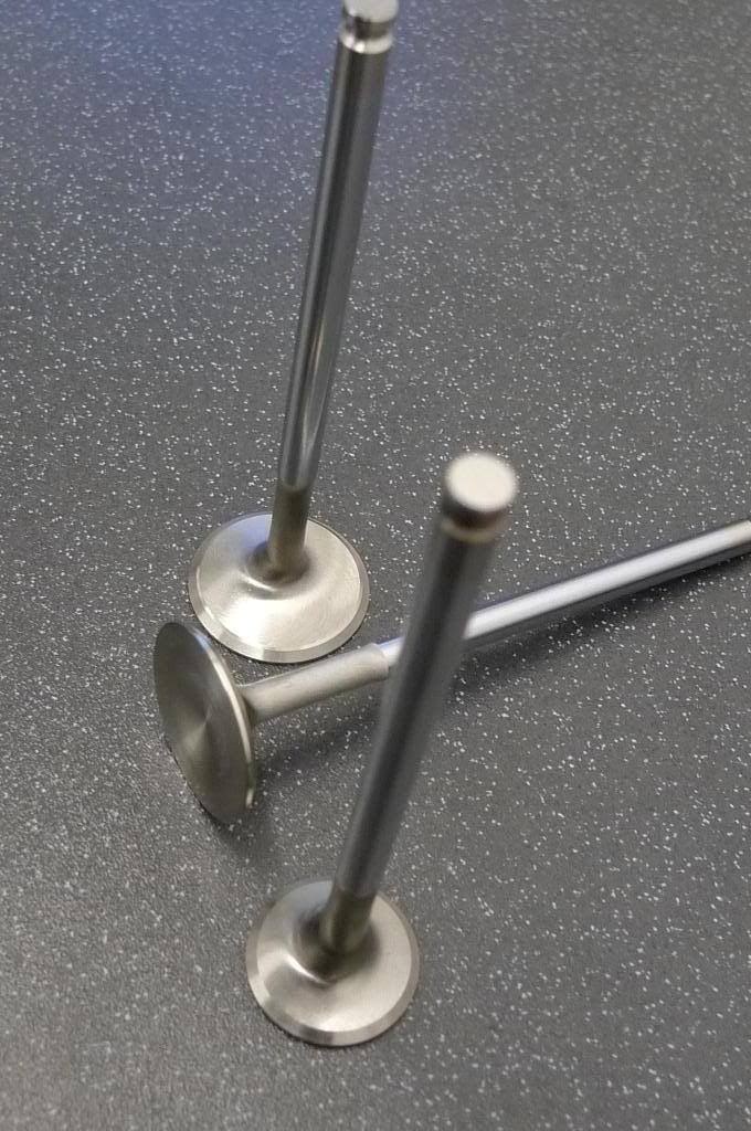
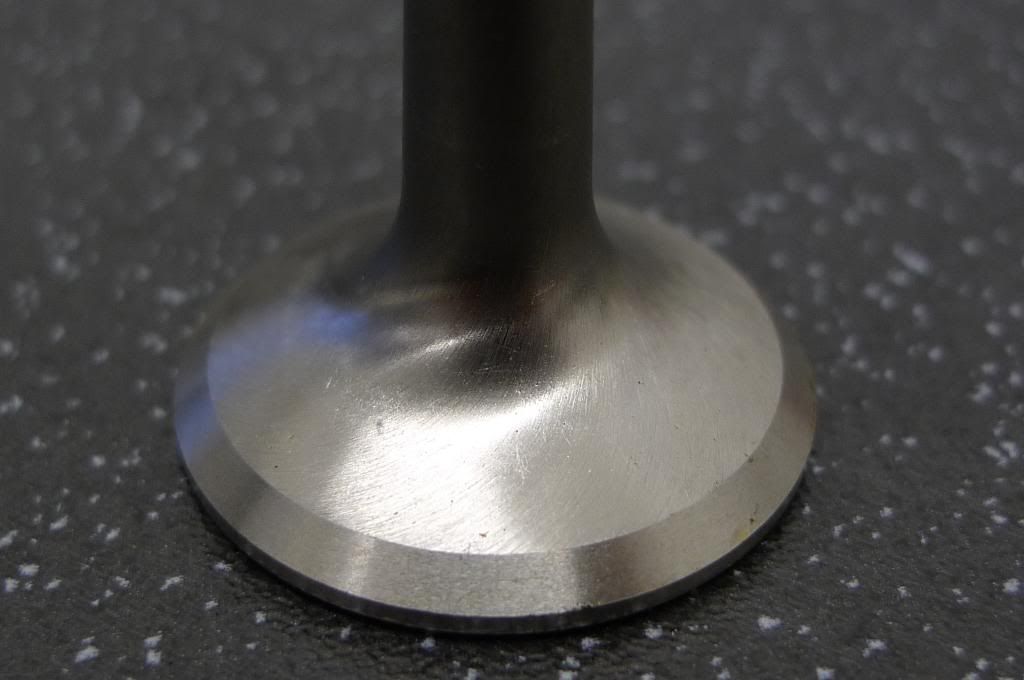
Also available are Nimonic exhaust valves, nice, light and swirl polished on the back of the heads on the standard size and they can be made in bigger diameters if you need a big valve head for quicker turbo spool up time. The last set went out to a customer as quickly as they came in so we only had time to get these shots!

Photobucket

Photobucket


To finish things off with the ultimate in valve reaction time and lightness are these new tappet buckets with tiny shims which go underneath and sit on top of the valve stem. Buckets are anti-friction coated and the weight saving is well worth having.


Prices will be uploaded on the website.

Monday, 8 March 2010

Intercooler theory and practice Part 1

This is a reprint of a small three part series I wrote on intercoolers so some may have read it before.

Abbreviations:

IC = Intercooler

Ambient = The temp of the air outside the car

Charge air = the air coming from the turbo to the engine

Tubes = These are the passageways that the charge air goes through within the intercooler.

AKA = As commonly known as...

CFM = Cubic feet per Minute (A measure of airflow)


I don't like imperial measurements, we (in the UK) have been Metric since 1971. BUT for the sake of simplicity here I am going to write in inches (") because it makes the numbers easier to digest for you.


Ok, let's start with the basics, the turbo on an engine compresses the air so more of it can be forced into the engine: More air (and petrol to match) = more power.

The main trade off is that compressing air also makes it hot, this is where the intercooler comes in - to cool the charge air. Cool air = more power AND reliability - hot air causes uncontrolled detonation within the combustion chamber which in turn leads to major engine damage and failure. Colder air is more dense (It contains more oxygen) so it gives more power.

The intercooler must meet two criteria, the first we just covered, the second is where a lot of people mess up: *It must be able to flow enough air for the engine to breathe properly*, get it too small and you will strangle the engine and throw away potential power.

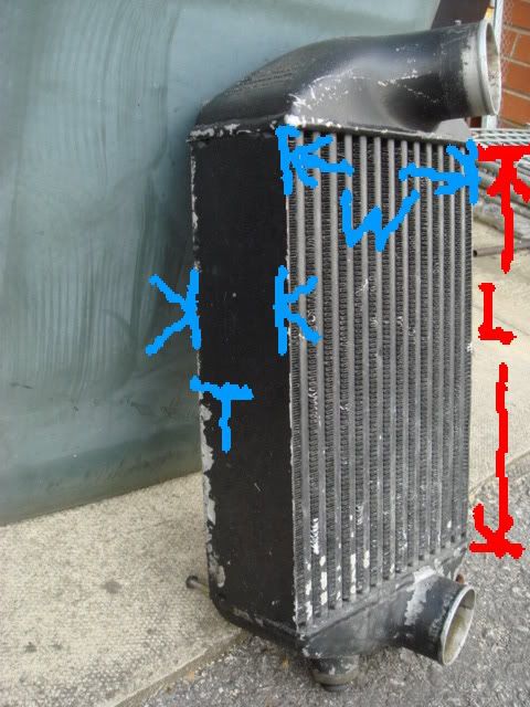
Here is how you label the dimensions of an intercooler:
Photobucket


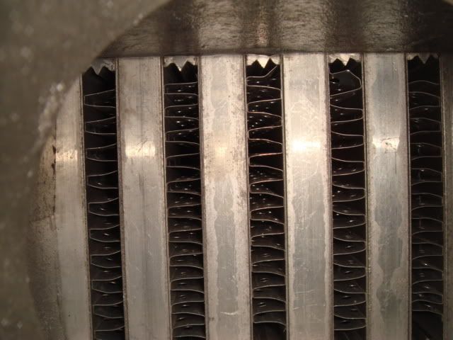
Let's look at a 'cooler in detail, there are two types of core: Bar & plate and tube & fin, it refers to the way they are manufactured and the shape of the tubes, B&P is more desireable as it flows better.

Bar and plate detail:

Photobucket

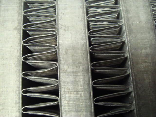
Tube and fin detail (an integrale IC):

Photobucket


Take a look at the zig-zag fins, these are known as 'Turbulators' or just fins, this is because they cause turbulance in the air. Basically the hot air hits and bounces over the turbulators as it goes through the tubes, when it does this it loses its heat to them, the fins then pass this heat (by convection) to the outside of the cooler, a similar process then happens - cooler ambient air passes through the external fins and cools them.

It is all down to heat transfer, basically an intercooler is a large heat sink, it takes the heat from the air within it then holds it until it is cooled by the air outside. The next facts are very important:

Turbulators slow the air to take the heat from them, the longer the tubes, the more you slow down the air, (velocity) do we want the air to slow right down? Of course not!! Slow lazy air = bad throttle response, AKA: Turbolag. Loss of power, response, economy etc.

FACT:
In a good efficient core the majority of air cooling is done in the first few inches of tube.

The rest is mainly waste, yes it drops the temp a little bit more, but nothing worth shouting about and is more than offset by the fact that that the air has practically gone to sleep....

What is a good figure here? About 7 to 8 inches, 12 - 16 as a max.

7 - 8"? Really?

Yep.

So why do aftermarket manufacturers make 'double pass' intercoolers which make the air go through 48" of tube and a U bend?


To make money out of people who don't know anything about ICs. Take a look here:

Photobucket


Will there be any flow figures (CFM)? Pressure drop? MPG? Power? Nope.
If you see a double pass intercooler for sale then just leave it on the shelf please, hopefully someone will melt it down and make something useful from it.


Please go to Part 2.

.

Intercooler theory and practice Part 2

Fact:
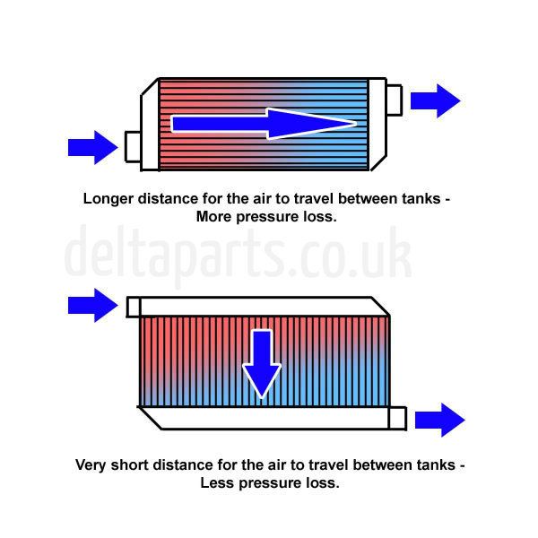
It's the number of tubes, not the length of them which matters.

To make a basic comparison, you have a guy who can run a marathon and you stick a drinking straw in his mouth, tell him to breathe through it and send him off, he gets 1/2 a mile before collapsing with exhaustion, why? Because he cannot get enough air to his lungs, so you pick him up, dust him off and give him a drink and a rest then stick a 3" pipe in his mouth (!!) and send him on his way again, he finishes the 5 mile marathon..... Your engine is just like the marathon runner.


Now for some basic maths, if you look inside a 'cooler:

Photobucket


You will see that roughly half is tube and half is blank, so only about 50% of the total area will actually flow air. Lets take the integrale cooler and compare it, a quick sum gives us sq" remember, only is half is tube so:

8 x 3 (x .5) so = 12sq"

This:


Is a pathetic 7.5 sq" (6 x 2.5 x .5) So although it looks bigger it will actually flow less air...


And then we return to this complete mess of an attempt, oh yes, the good old 3 x 12 x 24 double pass! (oh my god):

Photobucket

The air has to travel a whopping 48" (4 times further than an integrale IC) to get through it and it has a flow area of 9".
It flows less air than the OE cooler.
Jeez, I bet you could measure the turbo lag with an egg timer.

Turbo lag

Yes we just brushed on it there, you wanna know where lag comes from where tube area and pipe diameters are concerned? Well I'll let you into a secret, lag comes from the fact that not enough air can get through in the first place, not too much volume.....

Photobucket


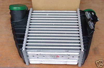
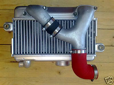
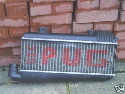
How do we know for certain we are on the right track? Where to look for good designs? Other newer cars of course, here are a few good examples:

Photobucket

Photobucket

Photobucket


The first one is a VW, check out the well shaped end tanks, designed to give well balanced flow to all the tubes. Also note Subarus nice job, short tubes, compact and the idea of twin pipes to equalise the flow again. The Pug one is just good basic design, tapered end tanks, lots of tubes, a very bad 90' bend on the end pipe, but still, you get the idea.

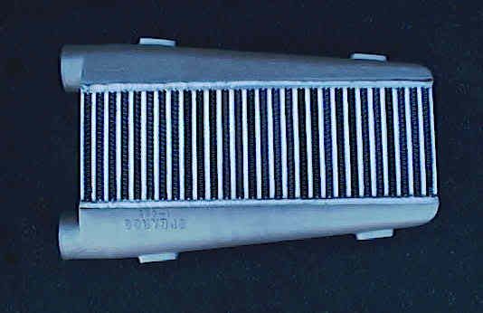
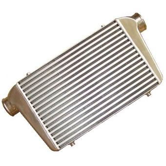
So, an off-the-shelf good design? Let's look at this:

Proposed  IC for integrale

Core size is 3 x 18


This looks like a good design, 3" thick x 12 wide and 16" long tubes:

Photobucket


Now you've just got to do the hard bit - fitting it in the cramped space......

Sunday, 7 March 2010

Intercooler theory and practice Part 3

Ducting is very important, especially if your IC is small and/or thick. Some people remove the duct from the integrale IC and then wonder why there car slows down as the intake temps go up...

FMICs cannot always be ducted easily, the air can go around them instead of through - which it does as it will always take the easiest path.


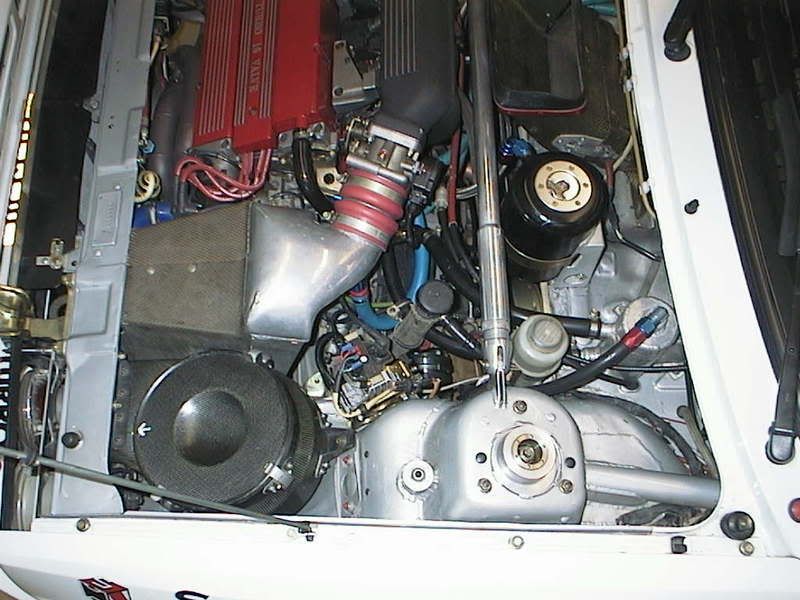
Grp A integrale, this has a small compact intercooler so they had to make the best of it with an excellent duct, see how it is smaller at the entrance than where it meets the 'cooler face, the air has no way of whirling round and coming back out, it is forced through the intercooler matrix where it cools it down:


Photobucket


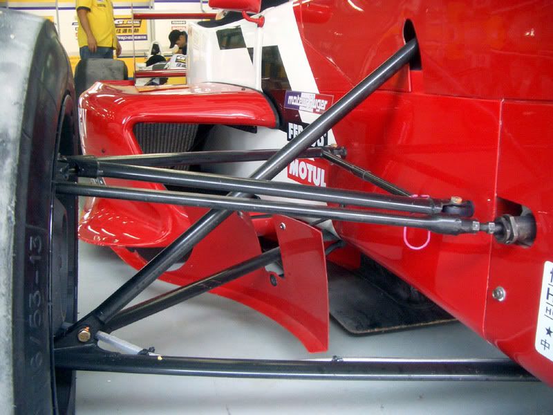
Ducting on a race car:

Photobucket


See how the rad is fitted at an angle? This makes the air struggle to get through the core and gives better cooling, it also allows a bigger core to be fitted in the same height.

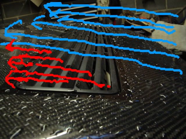
And finally here is what happens on the front of an integrale:

Photobucket

The cooling air goes throught the rad and intercooler and is then dragged back out of the engine bay by the air passing over the louvres.


So does the theory work?

Photobucket

Of course it does ;-)

http://www.youtube.com/user/Evoluzione2?feature=mhw4#p/u/4/mYEyAaqBbd4

Saturday, 20 February 2010

Evo 2 blown head gasket

Nothing really out of the ordinary, it came in sounding like Ivor the Engine (apologies to our overseas and younger readers: Steam powered locomotive)

And as you can see the result of running too much boost on an old engine with stock head gasket is:


On removing the front bumper I was confronted with this:


As you can see it is the Bertone symbol sprayed onto the front crossmember, apparently all Evos made after Lancia officially closed the Chivasso plant were sprayed by Bertone. Maggiora assembled the car bare, then they were loaded onto a truck and sent to Bertone to be sprayed, then returned and the car was then put on the Production line. Side skirts, spoilers, bumpers, bonnet grilles were sprayed separately off the car, fitted, then quality controlled/checked and road tested on some local roads and on the Chivasso test track.


Anyhow, back to the job: The head was stripped and cleaned for inspection, skimmed, new guides fitted, valves and seats re-cut, reassembled and shimmed up ready to go back. Once it was back on the block a new water pump, belts and all bearings were fitted.
Is this any better than what your local garage would do? I have a great relationship with the local garages around here, but after seeing them take a complete head from a car with a blown head gasket which was full of emulsified oil and put it back on again as it was, well you just wouldn't do that with a 15yr old 16v Lancia head - the guides will be worn out and the valve seats pitted for sure, it's also prudent to check for wear on the cams and cracks in the combustion chamber too, a common failure of these heads.


While we were waiting for the head being skimmed we also cured the rust problem on the bootlid - the usual area on the bottom corner and fitted one of our rear bumpers, resprayed and head re-fitted it is all ready for pick up.


The recess where the glass sits is filled with Waxoyl before the rear screen is re-fitted:


You pays your money, you take your chances.....


Thankyou to Paul Baker for the Bertone info.

Beware the armchair expert

Ah yes, every forum has at least one, if it is a large forum then there could be many.

They will quote something they read on another forum or something someone told them as if they they just did the job themselves. Before taking any notice of such people ask them to prove their theories, it will soon go quiet.


An armchair theorist porting and polishing his tailpipe whilst filling up with hot air yesterday:


Hmmm, nothing really floating my boat recently music-wise so lets go back in time with a classic just for the Keyboard Warrior:

http://www.youtube.com/watch?v=1g09GzbctlA

.

Monday, 11 January 2010

Deltaparts Developement car


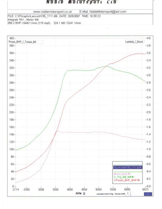
Currently reckoned to be the quickest 16v in the country is our long suffering developement car. It was never intended to be much special, bought as an abandoned project a few years ago when nothing more than stock apart from a partly fitted cage. Every panel on it is a different shade of Rosso 155, but it's relatively rust free and just refuses to die despite us never re-building the engine and it running well over 360bhp on standard internals - a testomony to strength of the Fiat/Lancia Twin cam.


It's been quite enjoyable just to buy someone elses quality part or design and build your own, bolt them on and measure the results, it has got a bit out of hand though and I think a new engine will be completed and fitted sometime this year, more power will be easy - just bolt on a bigger turbo, although if we have time it would be better to do some accompanying mods too. The old 16v has proved a few theorists wrong. Theories smashed were that you won't get stock rods and pistons to cope with over 300bhp, large intercoolers cause lag and that there is no way you will get that amount of power from the stock sized Garret T3 (this output I believe is a world first).

After studying and modifying naturally aspirated engines I applied the same techniques to the turbocharged Lampredi Twin-cam, the basic school of thought here is just as simple: Make the passages which carry air able to carry more, then match it with the equivalent increase in fuel. If you never lose sight of this simple rule you won't fail and if you want maximum efficiency then examine every single restriction and improve it. It really isn't difficult. So how did I go about this?
Well, going backwards from the 3" exhaust, through the equal length ceramic coated tubular manifold into the cylinder head which was gasflowed in house, controlled with bespoke high lift cams we move on to a matched and blended intake manifold with bigger injectors, ported throttle body, 3" intake pipework to the specially designed non restrictive downflow intercooler. Before that comes the stock sized T3 turbo (apart from 360' bearing, staggered oil seal and re-shaped/blended housings) and finally drawn through a rather large and properly sized K&N air filter.
Everything is controlled by a Motec ECU and the engine cooled by an aluminium radiator which incorporates the oil cooler in the same unit.
Ok, there is the occasional slight trade secret here and there in that mix, but there are the basics of it, sound simple? Pretty much so I think, just good old fashioned tuning theory, nothing more. The secret to keeping an engine in one piece is no restrictions, a cool intake charge and a damn good map.

Sadly when the car was mapped we didn't realise we had a small hole in a boost hose, this prevented the engine from receiving the full amount of pressure so we never knew what its genuine output was, you can see the torque and the boost drop off on the graph below. The rolling road we were on had just been recalibrated following it being flooded out in a storm!


16v on RR Sept 07
Would I recommend anyone push stock engine internals to these limits? Certainly not, this is just an old engine which we bolted some goodies onto to see what they would do, we had to do it this way to prove they worked. If we started from scratch with a whole host of new bits and pieces how would we know what was working well and what wasn't? By building it up this way we know and if the old engine blew it wouldn't be any problem, it owes us nothing.


The suspension is quite special, it features the first of a new generation of Intrax inverted coilovers all round which were built by Intrax and then dialled in specifically on the car by company owner and long time successful circuit racer Hank Thuis, I took it over there for them to work on it and they did a great job.

The front ARB has been shortened to increase its strength, drop links added which connect it to the strengthened suspension arms. A castor kit was also made and fitted. At the rear it features GrpA style transverse suspension arms, diff cradle, lower brace and a 19mm anti-roll bar, I would like to make some forward facing diagonal braces to the front (from the diff cradle to the cills) to finish of the rear and eradicate any movement.

The handling and grip need to be felt to be believed, front to rear traction 'slippage' is controlled by a viscous coupler which we had replenished with new fluid of a higher torque rating, the way it sticks to the tarmac is amazing, understeer is practically non-existant. There are still the Polybushes to get rid of as they are now the weak link, a sensitive driver (not me!) can feel the movement and there are witness marks at the rear where you can see it, some solid bearings will be fitted here this year. What is also helping the car handle is the Sparco cage, it stiffens the shell massively, this along with lightweight composite wings, bootlid and bonnet ensures the suspension does its work properly.
Currently being tested on the car is an aerodynamic front undertray, with more products being designed and made right now.

Search This Blog

About Me

My photo
Welcome to the Deltaparts Blog, here you will find, well, anything which is on my mind I guess, but mainly things to do with the Lancia Delta integrale and in particular anything to do with my business, Deltaparts. It will be a bit irregular as it's not every day (or even week) that something worth mentioning happens. I would like to try and make it interesting - at least to some people anyhow, but also hopefully accessible and readable for the average 'man on the street' so I won't bore you with loads of large words, bombastic overblown sentences or technical jargon. I will describe on here how lots of the parts that we sell came about as there isn't room on the website ( www.deltaparts.co.uk ) to explain. I hope you enjoy reading it as I do writing it, when something becomes a chore you know it's time to stop doing it....